Resistance
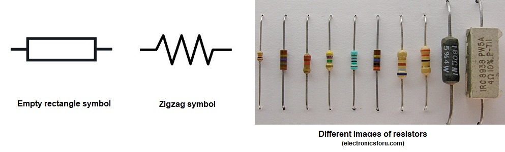
Resistance is usually indicated symbolically on an electrical drawing by one of two ways. An unfilled rectangle is commonly used. A zigzag line may also be used.
Resistance can be in the form of various components. A resistor may be placed in the circuit, or the circuit might contain other devices that have resistance.
Other resistor images used to limit or reduce the current in a circuit to accomplish a purpose. Resistors are also used to modify the functions of different parts of a circuit or a device. Most resistors are color coded if the value of resistance is not stated, which is in Ohms.
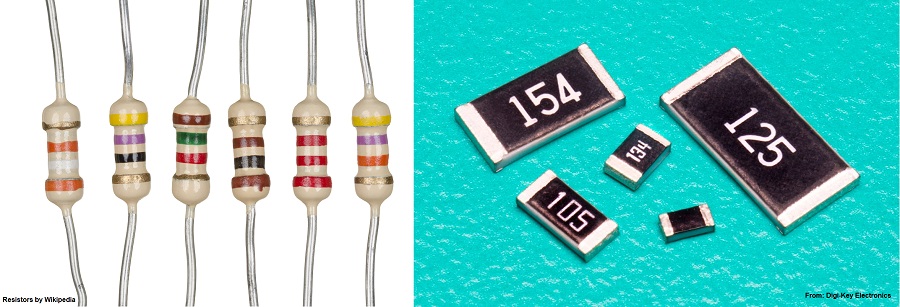
You notice that some resistors, if the resistance value is not indicated numerically, are color coded. These indicate the resistance value and other relevant information you need to know to be able to effectively use it in the right place and where it is needed. Below are the colors, their numeric values and their meanings.
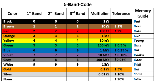
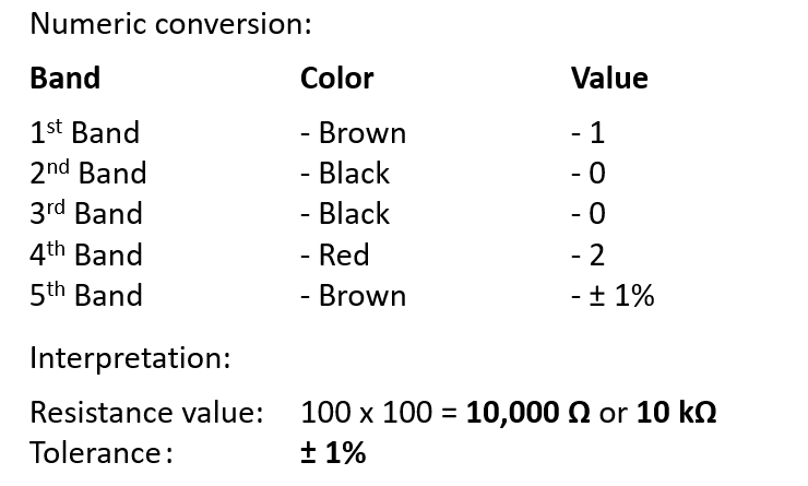
Here is an example of a color-coded resistor along with the interpretation of the codes.
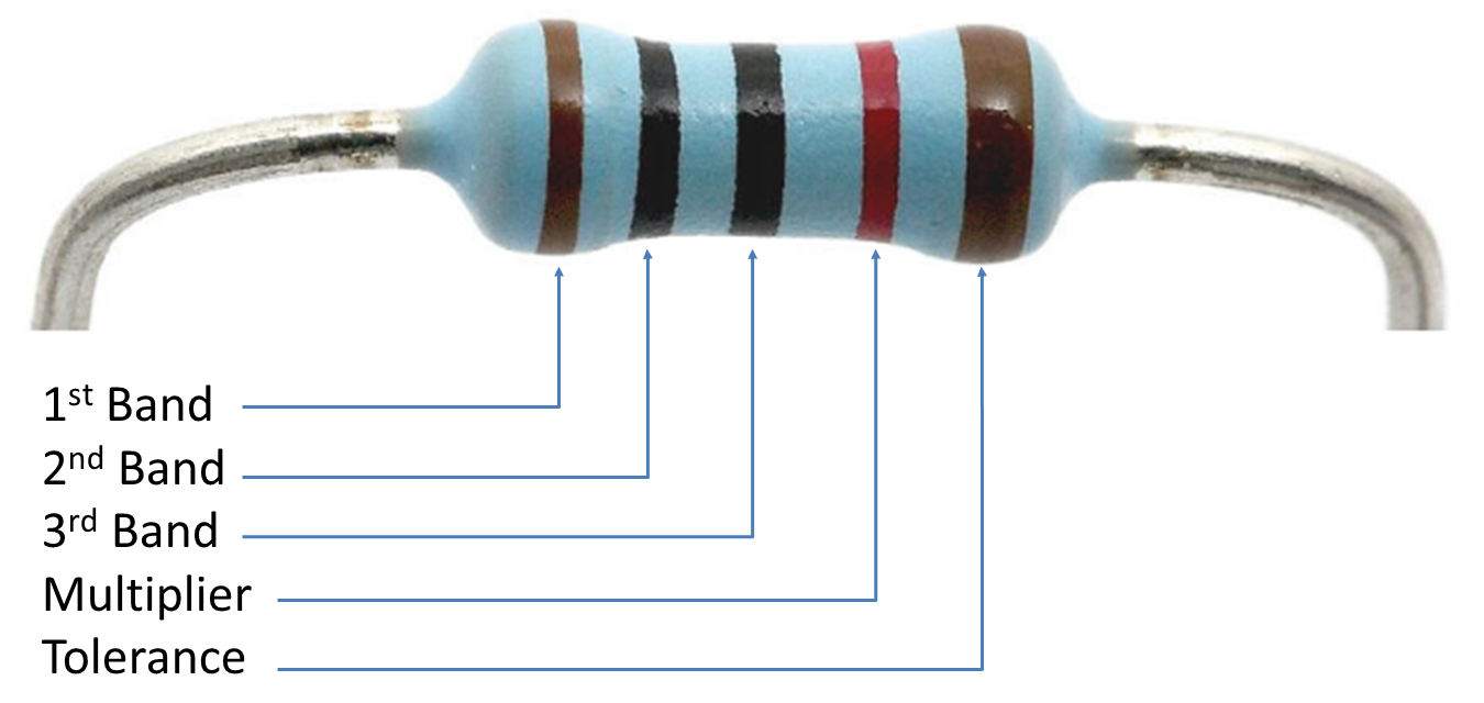
Here is an example of a color-coded resistor along with the interpretation of the codes.
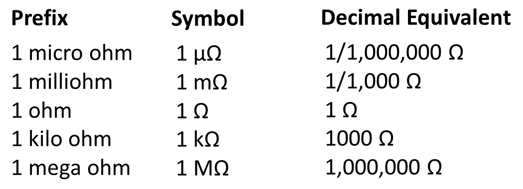
The table below explains the unit used in measuring resistance where prefixes were used when dealing with very small or large values of resistance.